The Ebyte E840-DTU(EC05-485)E data transmission terminal is a compact, high-performance 4G DTU data transmission terminal device that uses 4G CAT1 technology and has the characteristics of small size, high speed, low latency and easy use. Simple configuration can achieve two-way transparent transmission between serial port devices and network servers. The product uses 2.54mm spring-loaded terminals for easy wiring, supports guide rail and positioning hole installation, and can be easily integrated into IoT projects. In this article, we introduce the quick test method of E840-DTU(EC05-485)E in HTTP mode.
First, connect the device under test to the power supply and to the 485-to-USB module, as shown in Figure 1 below.
Figure 1
Insert the 485 to USB module into the computer and make sure the device is powered on. Open the product configuration host computer, select the correct COM port in the upper left corner, the device default baud rate is 115200, click OPEN to open the port. Then click AT mode in the upper right corner to enter AT mode, as shown in Figure 2 below. After successfully entering AT mode, the words AT mode successfully will be displayed in the log window, as shown in Figure 3 below.
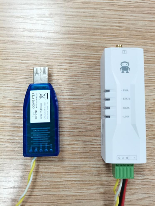
Figure 2
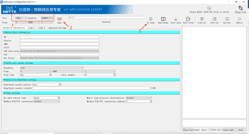
Figure 3
Click Read prams in the upper right corner, wait for all parameters to be read, and then select LINK 1 to configure the parameters, as shown in Figure 4 below.
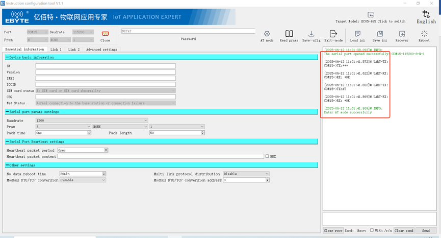
Figure 4
Select HTTP Client protocol in the Protocol option, as shown in Figure 5. After the modification is completed, the “HTTP Connection Parameters” will pop up automatically, as shown in Figure 6.
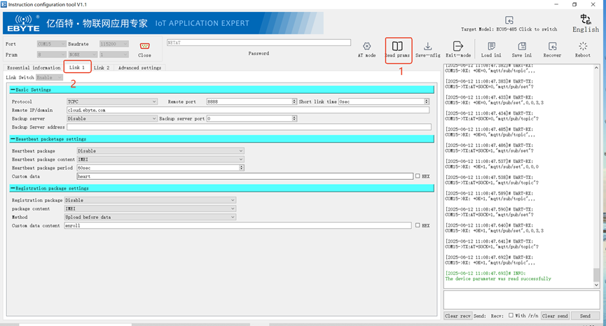
Figure 5
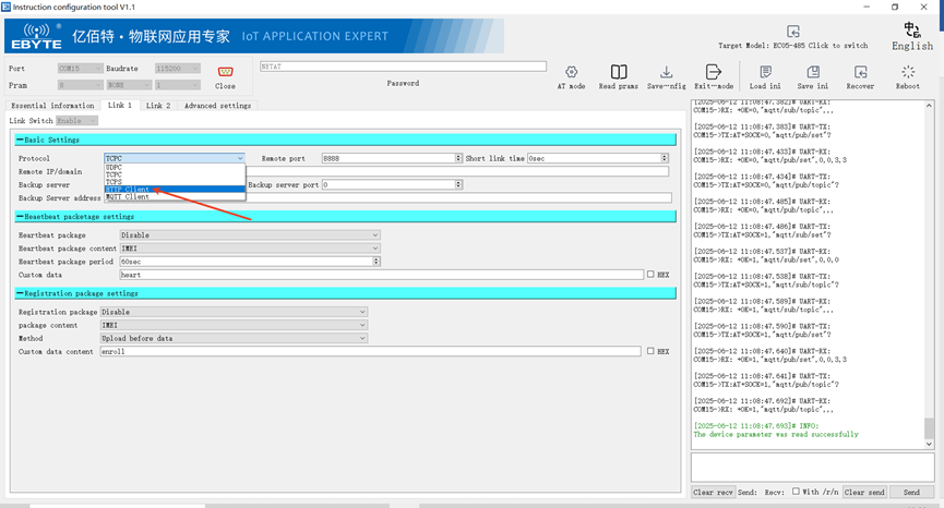
Figure 6
First, set the “Server Address” and “Destination Port” as shown in Figure 7. Next, set the “HTTP Transport Method” to “GET”, set the “URL” to “/text”, and finally, set the “HTTP Header Content”. The standard HTTP format should be “Host: Server Address” as shown in Figure 8. Please note that this is just a demonstration of the HTTP function. In actual settings, please set it according to your actual situation.
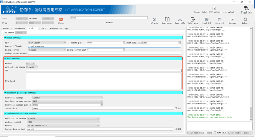
Figure 7
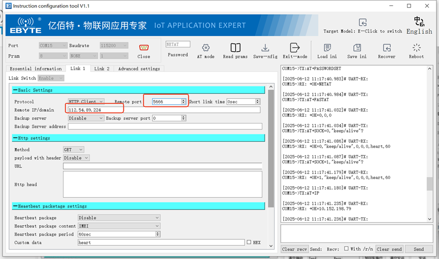
Figure 8
Click Save in the top right corner once the settings are finished. Restart the device after saving, as illustrated in Figure 9 below.
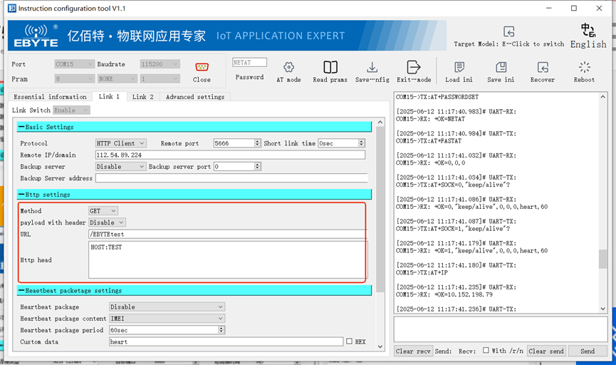
Figure 9
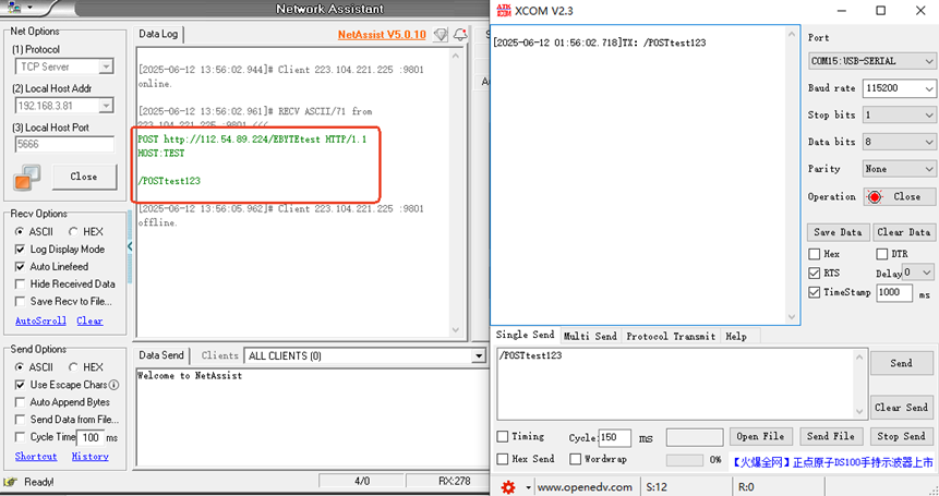
Wait for a while, and when the STATE light of the device changes from flashing to solid on, it means that the product is connected successfully. Next, we also use the network debugging assistant to simulate the HTTP server receiving data. Finally, open the serial port debugging tool software, send any data, and check whether the HTTP protocol packet sent successfully can be received in the network debugging assistant.
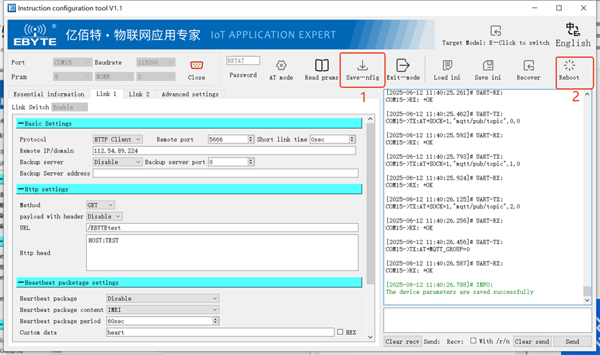
Figure 10
The HTTP function successfully issued a GET request to the server, as seen in Figure 10 above, and the server in turn received the HTTP GET request.
Next, test POST, change the “HTTP transmission method” of the device to “POST”, then click Save Parameters, and restart the device after saving successfully, as shown in Figure 11 below.
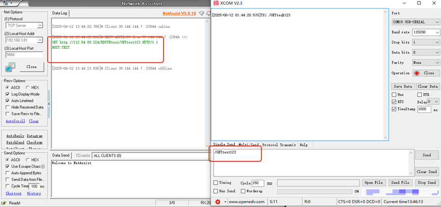
Figure 11
Wait for a while, and when the STATE light of the device changes from flashing to solid on, it means that the product is connected successfully. Still use the network debugging assistant to simulate the HTTP server to receive data. Open the serial port debugging tool software, send any data, and observe that the server receives the POST data sent by the device, as shown in Figure 12 below.
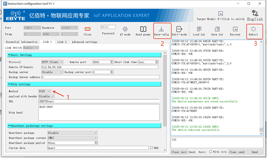
Figure 12