
Computer-aided design(CAD) and Computer-aided Manufacturing(CAM) are two dynamic duos in precision manufacturing. First, designers or engineers use suitable software to create the 2D and 3D drawings of the parts to be manufactured. Then, CAM system software converts the design into CNC programs, which control the machining operations like milling, drilling, turning, etc.
Although CAD and CAM systems are distinct in terms of their functions, both of them have the same end goal; precision & speed in manufacturing processes.
Furthermore, you will know CAD and CAM interrelation, their working mechanism, and why you might need to use CAD CAM manufacturing.
What is CAD CAM Manufacturing?
CAD/CAM manufacturing refers to the production of mechanical parts and products with the integration of computer tools, which minimizes human errors and provides high accuracy & speed. In both the design creation & process handling, CAD and CAM softwares are the key elements.
CAD CAM manufacturing
You also need to consider the manufacturability of design and optimization accordingly before converting the CAD format drawings into CNC files.
Moreover, CAD CAM manufacturing is not only for conventional CNC equipment, it is also used in robotics machining, sheet metal operations, and 3D printing.
How CAD and CAM Work Together?
CAD software like AutoCAD, CATIA, and SolidWorks are used to make engineering drawings (2D &3D), outlining all dimensions, features, and material specifications. These designs are easily changeable and can be modified by simply altering the design variables.
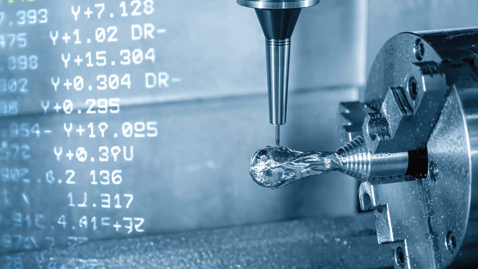
Next, manufacturers need precise codes (or instructions) to convert those engineering CAD designs into parts or products, which are done by CAM systems. It generates lines of instructions that control the tool movement, material removal, tolerances, and auxiliary operations
CAD CAM manufacturing
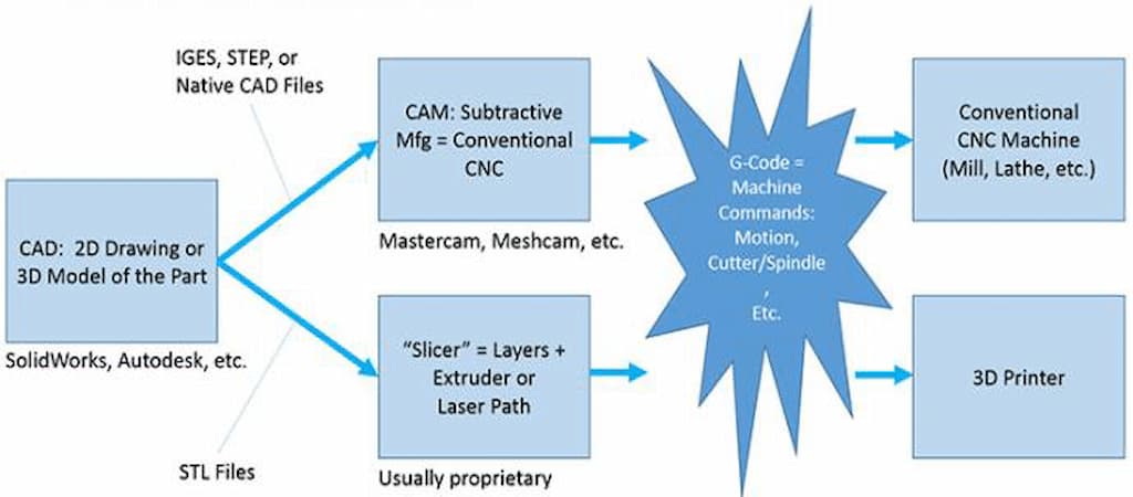
If we talk about the formats of files, CAD designs typically involve DFX, SLDPRT, STL, DWG, and STEP file formats. These are not directly readable for the CNC machines. Here, CAM systems process them and convert them into CNC file format, known as G-codes. Often, you can directly use CAM extensions in design software like Fusion 360 to change the format without transferring the file into another software.
The file is then transferred to the CNC control unit, which controls the machining operations and auxiliary functions of CNC equipment until the designed shape is achieved.
Difference between CAD and CNC File Formats
First, you need to understand that CAD file formats ( or file extensions) like .sldprt from SolidWorks and .dwg or .dfx from AutoCAD are completely different from CNC file formats (or extensions). These kinds of files can not be directly input into the CNC system. Instead, they are converted into compatible CNC file types like .nc or .gcode. The G-code commands control the tool movements, speeds, and tool paths.
Now, let’s look at their major differences through a comparative table;
| Aspect | CAD File Formats | CNC File Formats |
| Purpose | It defines part geometry, dimensions, and features. | Machine instructions for tool paths and operations. |
| Formats | STEP (.stp), IGES (.igs), DWG, DXF, etc. | G-code (.nc, .gcode |
| Data Content | Geometric data, material properties, tolerances, and metadata. | Commands for coordinates, feed rates, spindle speeds, and tool changes. |
| Interoperability | Neutral formats like STEP ensure compatibility across multiple platforms. | G-code is standardized but varies slightly by machine controller characteristics. |
| Creation Process | Designed in CAD software and imported into CAM for toolpath generation. | Generated by CAM software or manually edited. |
| Role in Workflow | Foundation for design, simulation, and analysis. | Guides CNC machines in physical (In-factory) production |
Benefits of Computer-Aided Manufacturing(CAM) and Where It is Used?
Applications of computer-aided manufacturing
Unlike laborious conventional manufacturing processes, CAM emphasizes automation by allowing computer-controlled movement of tools and machining systems. It minimizes the risk of human error and delivers consistent results.
The following are the key advantages of integrating CAD and CAM into manufacturing;
Precision and Efficiency
The error reduction in handling the manufacturing cycles results in high-precision parts, generally down to ±0.025 mm. Additionally, the automatic movement of the tool allows for faster cycles and improves the overall efficiency of the process.
Quality Surface Finish
Compared to manual machining, finishes are superior and can be customized for desired texture as well.
Consistency
Since the same tooling and CNC codes run the operations repeatedly, there are no variations in features, accuracy, and performance of parts produced through computer-aided manufacturing.
Operation Saftey
There is much less human intervention in the machining process directly, which reduces the risk associated with safety.
Cost Advantages
CAM also helps to optimize the tool path for minimal material waste while shaping the workpiece. Additionally, it reduces downtime and consistently runs multiple operations in a single setup. All of these reduce the per/part cost.
Material Flexibility
CAM manufacturing is not limited to any specific material type. It works well with metal, composites, plastics, rubbers, and other raw materials.
Furthermore, the use of CAD and CAM is diverse. It is applicable to make high-precision parts for automotive, aerospace, medical, robotics, electronics, defense, and many more industries. Basically, those applications where tight tolerances and consistency matter for desired performance.